Solo 155 - Manuale d'uso - Pagina 22


Indice:
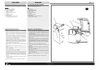
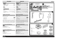
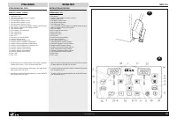
- Pagina 3 – DISEGNO ILLUSTRATIVO DELLA MACCHINA; ILLUSTRATIVE MACHINE DRAWING; TECHNICAL CHARACTERISTICS; D E
- Pagina 5 – DATI TECNICI; ÄÀÍÍÛÅ ÒÀÁËÈ÷ÊÈ; TECHNICAL DATA
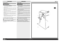
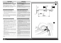
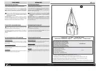
- Pagina 7 – DISIMBALLO; » DIMENSIONI D’INGOMBRO:; UNPACKING; » OVERALL DIMENSIONS:
- Pagina 9 – INSTALLAZIONE; COLLEGAMENTO ELETTRICO; INSTALLATION; ELECTRICAL CONNECTION
- Pagina 11 – INSTALLAZIONE FLANGIA; MONTAGGIO FLANGE; FITTING ADAPTERS; » Fig.10c shows the system for locking automobile wheels using the
- Pagina 13 – INSTALLAZIONE FLANGIA PNEUMATICA; FITTING THE PNEUMATIC ADAPTER
- Pagina 15 – MALFUNZIONAMENTI, LORO CAUSE E POSSIBILI RIMEDI; ITALIANO
- Pagina 17 – ISTRUZIONI PER L’USO; PANNELLO COMANDI - LEGENDA; INSTRUCTIONS FOR USE
- Pagina 19 – EQUILIBRATURA RUOTE; Accendere la macchina mediante l’interruttore principale.; WHEEL BALANCING; Switch on the machine with the main switch.; EQUILIBRAGE DES ROUES; Allumer la machine par l’interrupteur principal.
- Pagina 20 – SELEZIONE PROGRAMMA DI EQUILIBRATURA
- Pagina 24 – PROGRAMMA DI SEPARAZIONE DEI PESI
- Pagina 26 – OTTIMIZZAZIONE SQUILIBRIO
- Pagina 27 – CONFIGURAZIONE EQUILIBRATRICE
- Pagina 28 – TARATURA BASE DELLA MACCHINA; Prima fase di taratura: correzione squilibrio albero.; BASIC MACHINE CALIBRATION; First stage of calibration: shaft imbalance correction.
- Pagina 31 – AUTODIAGNOSI; on si la pédale est tirée vers le haut et oFF si la pédale est à repos
- Pagina 32 – UTILIZZO PROGRAMMA ALUDATA; START, en commençant ainsi le cycle de mesure.
- Pagina 33 – TABELLA OLII / OIL TABLE / TABLEAU DES HUILES; Ñìàçî÷íîå ìàñëî äëÿ ïíåâìàòè÷åñêîé ñèñòåìû; ESSO FEBIS K 32
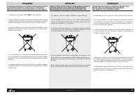
- Pagina 35 – » E’ obbligatorio non smaltire i RAEE (WEEE) come rifiuti urbani.
- Pagina 36 – ASSISTENZA TECNICA E PARTI DI RICAMBIO; TECHNICAL ASSISTANCE AND SPARE PARTS
- Pagina 38 – Declaración de Conformidad CE; persona autorizzata a costituire il fascicolo tecnico/; SICAM; person authorized to compile the technical file/; Marco Matteucci; Via della Costituzione 49
ITALIANO
ENGLISH
SBM 155
28
COD. 655632 Rev.0
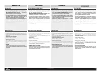
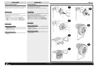
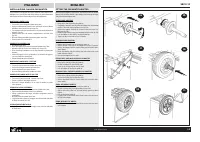
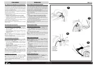
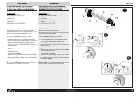
PROGRAMMAZIONE E FISSAGGIO PESI
ADESIVI CON CALIBRO SPECIALE PER
CERCHI IN ALLUMINIO O LEGA LEGGERA
CALIBRO (Fig.21a)
A: CORSOIO CALIBRO BASE
B: TESTINA CALIBRO POSIZIONE PESI
C: PINZA ESTERNA
D: POMELLO A VITE
E: TARGHETTA MILLIMETRATA
F: ESPULSORE
G: PINZA INTERNA PER FISSAGGIO PESO
H: IMPUGNATURA CON SEDE TARGHETTA
La macchina è fornita di un CALIBRO SPECIALE per la programmazione
ed il fissaggio dei pesi adesivi su cerchi in alluminio e lega leggera.
Questo calibro, previsto per l’utilizzo con i programmi alu 2, alu 3 e Pax 2,
permette di determinare con la massima precisione (e secondo la conformità
del cerchio) la posizione esatta di fissaggio del peso adesivo.
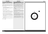
Osservare le figure 21a-21b e 21c e procedere come segue:
» programmare la macchina su ALU 2 (ved. fig.18);
» posizionare il calibro con la base (A) sul bordo interno del cerchio;
» facendo scorrere la base A sul cursore millimetrato (E) portare la pinza
esterna (C) sulla posizione desiderata e ottimale di fissaggio peso;
» fissare la base (A) con l’apposito pomello a vite (D);
» leggere la misura in mm e impostarla tramite tastiera sulla larghezza
cerchio (ved. fig.20c);
» fare un lancio di equilibratura: usciranno i valori del peso ( interno ed
esterno);
» portare in posizione la ruota e montare il peso (letto sul display esterno)
sulla pinza esterna (C);
» portare la base (A) sul bordo del cerchio (ore 12) e fissare il peso tramite
l’espulsore (F) (vedere fig.21b);
» portare in posizione la ruota e montare il peso (letto sul display interno)
sulla pinza interna (G);
» portare la testina calibro (B) sul bordo del cerchio e fissare il peso tramite
l’espulsore (F) (ved. fig.21c).
N.B.: Per i programmi ALU 3 e la procedura esterna rimane la stessa; per
l’interno fissare il peso a molletta sul bordo cerchio.
21a
21c
21b
PROGRAMMING AND FITTING ADHESIVE
WEIGHTS WITH THE SPECIAL GAUGE FOR
ALUMINIUM OR LIGHT ALLOY RIMS
GAUGE (Fig.21a)
A: GAUGE BASE CURSOR
B: WEIGHT POSITIONING GAUGE HEAD
C: OUTSIDE CLAW
D: SCREW KNOB
E: SCALE PLATE IN MILLIMETRES
F: EXTRUDER
G: INSIDE CLAW FOR FIXING WEIGHTS
H: GRIP WITH SCALE PLATE INSERT
A SPECIAL GAUGE is supplied with the machine for the ALU programs and
for fixing weights to aluminium and light alloy rims.
This gauge, designed for use in the ALU 2, ALU 3 and Pax 2 programs,
allows maximum precision (also in relation to the rim shape) when determin-
ing the position for fixing adhesive weights.
Look at figures 21a-21b and 21c and proceed as follows:
» Set the machine program to A L U 2 (see. fig.18).
» Position the gauge with its base at (A) on the inside edge of the rim.
» Slide the base A on the millimetre scale (E) and move the outside claw
(C) to the required and optimum position for fixing the weigh.
» Fix the base (A) using the screw knob (D).
» Read the measurement in mm and enter it as the rim width using the
keyboard (see fig.20c).
» Run a balancing cycle: the weight figures are given (internal and exter-
nal).
» Move the wheel into position and locate the weight (as read on the exter-
nal display) on the outside claw (C).
» Move the base (A) to the edge of the rim (12 o’clock) and fix the weight
using the extruder (F) (see fig. 21b).
» Move the wheel into position and locate the weight (as given on the in-
ternal display) on the inside claw (G).
» Move the gauge head (B) to the edge of the rim and fix the weight using
the extruder (F) (see fig. 21c).
N.B.: For the ALU-3 program the external procedure is the same, while for
the internal reading, fix the spring weight on the rim flange.
"Caricamento dell'istruzione" significa che è necessario attendere finché il file non è caricato e pronto per la lettura online. Alcune istruzioni sono molto grandi e il tempo di caricamento dipende dalla velocità della tua connessione a Internet.
Sommario
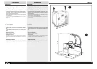
ITALIANO ENGLISH SBM 155 4 COD. 655632 Rev.0 1 DISEGNO ILLUSTRATIVO DELLA MACCHINA con indicazione delle principali parti componenti ai fini dell’uso LEGENDAA: INTERRUTTORE GENERALEB: CAVO DI ALIMENTAZIONEC: CRUSCOTTO PORTAPESID: PANNELLO COMANDIE: CARTER PROTEZIONE RUOTAF : FLANGIAG. CALIBRI AUTOMA...
ITALIANO ENGLISH SBM 155 6 COD. 655632 Rev.0 DATI TECNICI DIMENSIONIAltezza Max (con carter aperto) ............................................... 1800mmProfondità (con carter aperto) ................................................ 1260mmLarghezza (senza flangia) .....................................
ITALIANO ENGLISH SBM 155 8 COD. 655632 Rev.0 1800 900 500 1260 500 5 DISIMBALLO » Dopo avere tolto l’imballaggio (ved. fig.5) assicurarsi del’integrità della macchina controllando che non vi siano parti visibilmente danneggiate.In caso di dubbio non utilizzare la macchina e rivolgersi a personalepro...