OTTIMIZZAZIONE SQUILIBRIO - Solo 155 - Manuale d'uso - Pagina 26


Indice:
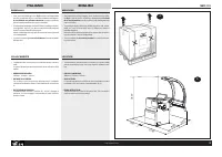
- Pagina 3 – DISEGNO ILLUSTRATIVO DELLA MACCHINA; ILLUSTRATIVE MACHINE DRAWING; TECHNICAL CHARACTERISTICS; D E
- Pagina 5 – DATI TECNICI; ÄÀÍÍÛÅ ÒÀÁËÈ÷ÊÈ; TECHNICAL DATA
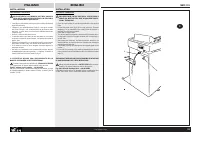
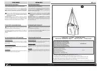
- Pagina 7 – DISIMBALLO; » DIMENSIONI D’INGOMBRO:; UNPACKING; » OVERALL DIMENSIONS:
- Pagina 9 – INSTALLAZIONE; COLLEGAMENTO ELETTRICO; INSTALLATION; ELECTRICAL CONNECTION
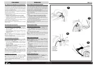
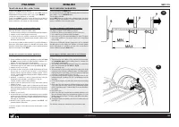
- Pagina 11 – INSTALLAZIONE FLANGIA; MONTAGGIO FLANGE; FITTING ADAPTERS; » Fig.10c shows the system for locking automobile wheels using the
- Pagina 13 – INSTALLAZIONE FLANGIA PNEUMATICA; FITTING THE PNEUMATIC ADAPTER
- Pagina 15 – MALFUNZIONAMENTI, LORO CAUSE E POSSIBILI RIMEDI; ITALIANO
- Pagina 17 – ISTRUZIONI PER L’USO; PANNELLO COMANDI - LEGENDA; INSTRUCTIONS FOR USE
- Pagina 19 – EQUILIBRATURA RUOTE; Accendere la macchina mediante l’interruttore principale.; WHEEL BALANCING; Switch on the machine with the main switch.; EQUILIBRAGE DES ROUES; Allumer la machine par l’interrupteur principal.
- Pagina 20 – SELEZIONE PROGRAMMA DI EQUILIBRATURA
- Pagina 24 – PROGRAMMA DI SEPARAZIONE DEI PESI
- Pagina 26 – OTTIMIZZAZIONE SQUILIBRIO
- Pagina 27 – CONFIGURAZIONE EQUILIBRATRICE
- Pagina 28 – TARATURA BASE DELLA MACCHINA; Prima fase di taratura: correzione squilibrio albero.; BASIC MACHINE CALIBRATION; First stage of calibration: shaft imbalance correction.
- Pagina 31 – AUTODIAGNOSI; on si la pédale est tirée vers le haut et oFF si la pédale est à repos
- Pagina 32 – UTILIZZO PROGRAMMA ALUDATA; START, en commençant ainsi le cycle de mesure.
- Pagina 33 – TABELLA OLII / OIL TABLE / TABLEAU DES HUILES; Ñìàçî÷íîå ìàñëî äëÿ ïíåâìàòè÷åñêîé ñèñòåìû; ESSO FEBIS K 32
- Pagina 35 – » E’ obbligatorio non smaltire i RAEE (WEEE) come rifiuti urbani.
- Pagina 36 – ASSISTENZA TECNICA E PARTI DI RICAMBIO; TECHNICAL ASSISTANCE AND SPARE PARTS
- Pagina 38 – Declaración de Conformidad CE; persona autorizzata a costituire il fascicolo tecnico/; SICAM; person authorized to compile the technical file/; Marco Matteucci; Via della Costituzione 49
ITALIANO
ENGLISH
FRANÇAIS
32
COD. 655632 Rev.0
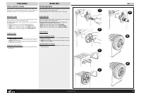
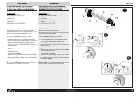
OTTIMIZZAZIONE SQUILIBRIO
Quando lo squilibrio misurato sulla ruota è molto elevato (es.: squilibrio statico > 50g) si consiglia
di eseguire la procedura di ottimizzazione squilibrio: il programma permette di ridurre lo squilibrio
totale della ruota compensando, quando possibile, lo squilibrio statico del pneumatico con quello
del cerchio. Necessita delle seguenti operazioni: un primo lancio di misura; una rotazione di 180°
del pneumatico sul cerchio; un secondo lancio di misura; una nuova rotazione del pneumatico sul
cerchio secondo quanto indicato dalla macchina; un ultimo lancio di verifica.
Per attivare la procedura di riduzione dello squilibrio statico premere il tasto OTTIMIZZAZIONE
(tasto 12 fig.18) e rilasciarlo immediatamente: sul display compare la scritta oPt1.
Fase 1: premere il tasto START per eseguire un primo lancio con la ruota da ottimizzare: al termine
del lancio sul display compare l’ indicazione oPt2.
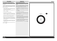
Fase 2: ruotare a mano la ruota in modo da portare la valvola in posizione ad “ore 12”; con la ruota
in questa posizione premere il tasto SPLIT (che presenta entrambi i led accesi) per memorizzare
la posizione di riferimento della ruota nel primo lancio: sul display compare la scritta oPt3; fare un
segno di riferimento sul pneumatico in corrispondenza della posizione della valvola.
Fase 3: togliere il cerchio dalla flangia e ruotare il pneumatico sul cerchio di 180 gradi (ci si può
aiutare con il segno fatto in precedenza, portando il segno stesso in posizione esattamente opposta
alla posizione della valvola). Rimontare il cerchio sulla flangia e riposizionare di nuovo la valvola
ad ‘ore 12’; mantenendo ferma la ruota in questa posizione, premere il tasto SPLIT (entrambi i led
accesi) per memorizzare la nuova posizione del cerchio sulla flangia: sul display compare la scritta
oPt 4.
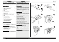
Fase 4: premere il tasto START per eseguire un nuovo lancio: al termine del lancio il display
visualizzerà la scritta oPt 5.
ATTENZIONE: per ottenere il migliore risultato possibile dall’operazione di riduzione dello squilibrio,
è necessario che le operazioni precedenti vengano eseguite con la massima precisione.
Premendo il tasto STOP al termine del secondo lancio, sui display compaiono le seguenti indicazioni:
- display destro: valore dello squilibrio statico attuale della ruota;
- display sinistro: valore dello squilibrio residuo minimo che è possibile ottenere con la
riduzione di squilibrio consigliata.
Visualizzare questi valori è utile per decidere se è conveniente proseguire nell’operazione di riduzione
dello squilibrio: (per lo stesso motivo, anche dopo il primo lancio è possibile, premendo il tasto
STOP, visualizzare sul display destro lo squilibrio statico della ruota per verificare se sia
effettivamente utile eseguire l’operazione di riduzione).
Fase 5: per procedere nella riduzione dello squilibrio, ruotare a mano la ruota in modo da portare in
posizione centrale i led di posizionamento sul display e contrassegnare il pneumatico nel punto
superiore (nella stessa posizione in cui normalmente si colloca il peso). Per ridurre lo squilibrio
togliere il cerchio dalla flangia e ruotare il pneumatico sul cerchio sino a far coincidere questo nuovo
contrassegno con la posizione della valvola. Rimontare il cerchio sulla flangia e posizionare di
nuovo la valvola ad “ore 12”; mantenendo ferma la ruota in questa posizione, premere il tasto SPLIT
(entrambi i led accesi) per memorizzare la nuova posizione del cerchio sulla flangia: sul display
compare la scritta oPt 6.
Fase 6: premere il tasto START per eseguire il lancio di verifica. Al termine del lancio di verifica,
lo squilibrio della ruota viene confrontato automaticamente con il valore dello squilibrio minimo
residuo: se la differenza fra questi due valori risulta inferiore alla massima tolleranza consentita, sul
display compare la scritta oPt yES; premendo il tasto STOP è comunque possibile visualizzare il
nuovo valore dello squilibrio statico attuale per verificare il risultato dell’ operazione eseguita.
Fase 7 : nel caso in cui la prima riduzione non sia stata soddisfacente, sul display compare di nuovo
la scritta oPt 5: in tal caso è possibile proseguire nell’operazione di riduzione ripetendo le operazioni
descritte a partire dalla fase 5. Quando non è più possibile ridurre ulteriormente lo squilibrio la
procedura termina:
- se l’ operazione è stata completata con successo il display visualizza oPt yES;
- in caso di insuccesso il display visualizza oPt Err indicando che è necessario ripetere l’ intera
procedura dall’ inizio.
Al termine dell’operazione di ottimizzazione premendo il tasto STOP si ritorna alla misura dei valori
di squilibrio ruota ed i display visualizzano lo squilibrio attuale della ruota.
In qualsiasi momento la pressione del tasto OTTIMIZZAZIONE interrompe il procedimento di
riduzione dello squilibrio ed il sistema ritorna alla misura dello squilibrio ruota.
OPTIMISING IMBALANCE
When the imbalance measured on a wheel is very high (e.g. static imbalance > 50g) the imbalance
optimization procedure is recommended. This program allows the reduction of the total imbalance
of the wheel by compensating, when possible, the static imbalance of the tire with that of the rim.
The following operations are required: an initial measuring cycle, rotation the tire on the rim by 180°,
a second measuring cycle, another rotation of the tire on the rim to the extent indicated by the
machine, and a final check measuring cycle.
To activate the static imbalance reduction procedure press the OPTIMIZATION button (button 12
fig.18) and release it immediately: the display reads oPt1.
Stage 1: Press the START button to run the first cycle with the wheel to be optimized: at the end of
the cycle the display reads oPt2.
Stage 2: Rotate the wheel by hand to bring the valve to the “12 o’clock” position. Press the SPLIT
key (which has both LED’s on) to memorize the wheel reference position for the first run. The display
reads oPt3. Mark a reference point on the tire itself at the valve position.
Stage 3: Remove the rim from the adapter and rotate the tire on the rim by 180° (refer to the mark made
on the tire, moving it to a position directly opposite the valve). Remount the rim on the adapter and
once more reposition the valve at 12 o’clock. Keeping the wheel in this position, press the SPLIT
key (which has both LED’s on) to memorize the new position of the rim on the adapter. The display
reads oPt 4.
Stage 4: Press the START button to run a new cycle. At the end of the cycle the display reads oPt5.
IMPORTANT: for best imbalance reduction results it is important that the operations described above
are carried out with the maximum precision.
Pressing the STOP button at the end of the second cycle displays the following information:
- Right display: current static imbalance reading for the wheel.
- Left display: minimal residual imbalance that can be achieved by applying the recommended
imbalance reduction.
Displaying these figures is useful for deciding if it is worth continuing the imbalance reduction
procedure (for the same reason, also after the first cycle the STOP button can be pressed to view
the static imbalance on the right display and thus check if it is effectively worth following the
reduction procedure).
Stage 5: To proceed with reduction of imbalance, rotate the wheel by hand to bring the positioning
LED’s on the display into a central position and mark the tire at the top (the same position the weight
is normally located). To reduce imbalance remove the rim from the adapter and rotate the tire on the
rim until the new mark is at the valve position. Remount the rim on the adapter and again position
the valve at 12 o’clock. Keeping the wheel in this position press the SPLIT key (with both LED’s
on) to memorize the new position of the rim on the adapter. The display reads oPt 6.
Stage 6: Press the START key to run a test cycle. At the end of the test cycle the wheel imbalance
is automatically compared with the minimum residual imbalance figure. If the difference between
these two values is less that the maximum permitted tolerance, the display reads oPt yES. By
pressing the STOP button it is in any case possible to display the new static imbalance figure in
order to verify the success of the procedure.
Stage 7 : If the first imbalance reduction cycle has not been satisfactory, the display again reads oPt
5. In this case it is possible to continue imbalance reduction by repeating the steps described above,
starting from stage 5. When it is not possible to further reduce imbalance the procedure terminates:
- It the procedure was completed with success the display reads oPt yES.
- If the procedure was unsuccessful the display reads oPt Err indicating that it is necessary to
repeat the entire procedure from the beginning.
At the end of optimization operations press the STOP button to return to wheel imbalance measuring
and the display shows the imbalance for the current wheel.
Pressing the OPTIMIZATION button at any time interrupts the imbalance reduction procedure and
the system reverts to wheel imbalance measuring mode.
OPTIMISATION DU BALOURD
Quand le balourd mesuré sur la roue est très élevé (ex.: balourd statique > 50g) il est conseillé
d’exécuter la procédure d’optimisation du balourd: le programme permet de réduire le balourd total
de la roue en compensant, lorsque c’est possible, le balourd statique du pneu par celui de la jante.
Exécuter les opérations suivantes: un premier lancer de mesure; une rotation de 180° du pneu sur
la jante; un deuxième lancer de mesure; une nouvelle rotation du pneu sur la jante selon l’indication
de la machine; un dernier lancer de vérification.
Pour activer la procédure de réduction du balourd statique presser la touche OPTIMISATION (tou-
che 12 fig.18) et la relâcher immédiatement: sur l’afficheur apparaîtra le mot oPt1.
Phase 1: presser la touche START pour exécuter un premier lancer avec la roue à optimiser: à la
fin du lancer sur l’afficheur apparaîtra l’indication oPt2.
Phase 2: faire tourner la roue à la main jusqu’à amener la soupape à la position “12 heures”; avec
la roue dans cette position presser la touche SPLIT (qui présente les deux leds allumées) pour
mémoriser la position de référence de la roue du premier lancer: sur l’afficheur apparaît le mot oPt3;
faire une marque de référence sur le pneu en correspondance de la position de la soupape.
Phase 3: ôter la jante du plateau et tourner le pneu sur la jante de 180 degrés (on peut s’aider par
la marque faite auparavant, en amenant celle-ci à la position opposée à celle de la soupape).
Remonter la jante sur le plateau et repositionner la soupape à ’12 heures’; en gardant la roue dans
cette position, taper la touche SPLIT (les deux leds allumées) pour mémoriser la nouvelle position
de la jante sur le plateau: sur l’afficheur apparaît le mot oPt 4.
Phase 4: presser la touche START pour exécuter un nouveau lancer: à la fin du lancer, l’afficheur
montrera oPt 5.
ATTENTION: pour obtenir le meilleur résultat possible de l’opération de réduction du balourd, il est
indispensable que les opérations qui précèdent soient exécutées avec le maximum de précision.
En pressant la touche STOP à la fin du deuxième lancer, les moniteurs montrent les indications
suivantes:
- moniteur à droite: valeur du balourd statique réel de la roue;
- moniteur à gauche: valeur du balourd résiduel minimum qu’il est possible d’obtenir avec la
réduction du balourd conseillée.
C’est utile d’afficher ces valeurs pour décider s’il convient de continuer l’opération de réduction du
balourd: (pour la même raison, il est possible aussi après le premier lancer, en pressant la touche
STOP, d’afficher sur le moniteur à droite le balourd statique de la roue pour vérifier s’il est vraiment
utile d’exécuter l’opération de réduction).
Phase 5: pour continuer l’opération de réduction du balourd, faire tourner la roue à la main jusqu’à
amener les leds de positionnement sur l’afficheur à la position centrale et marquer le pneu au point
supérieur (à la même position où on applique normalement la masse). Pour réduire le balourd, ôter
la jante du plateau et faire tourner le pneu sur la jante jusqu’à faire coïncider cette nouvelle marque
avec la position de la soupape. Remonter la jante sur le plateau et repositionner la soupape à “12
h”; en gardant la roue à cette position, presser la touche SPLIT (les deux leds allumées) pour
mémoriser la nouvelle position de la jante sur le plateau: sur le moniteur apparaît oPt 6.
Phase 6: presser la touche START pour exécuter un lancer de vérification. A la fin du lancer de
vérification, le balourd de la roue est comparé automatiquement avec la valeur du balourd résiduel
minimum: si la différence entre ces deux valeurs résulte inférieure à la tolérance maximum admise,
le moniteur affiche oPt yES; en pressant la touche STOP il est possible d’afficher la nouvelle valeur
du balourd statique réel pour vérifier le résultat de l’opération exécutée.
Phase 7 : dans le cas où la première réduction n’a pas été satisfaisante, l’afficheur montre à
nouveau oPt 5: dans ce cas il est possible de continuer l’opération de réduction en répétant les
opérations décrites à partir de la phase 5. Quand il n’est plus possible de réduire davantage le
balourd, la procédure termine:
- si l’ opération a réussi le moniteur affiche oPt yES;
- dans le cas contraire le moniteur affiche oPt Err indiquant qu’il faut répéter toute la procédure
depuis le début.
A la fin de l’opération d’optimisation, en tapant sur la touche STOP on revient à la mesure des
valeurs de balourd de la roue et les moniteurs affichent le balourd réel de la roue.
A tout moment, la pression de la touche OPTIMISATION interrompt la procédure de réduction du
balourd et le système revient à la mesure du balourd de la roue.
"Caricamento dell'istruzione" significa che è necessario attendere finché il file non è caricato e pronto per la lettura online. Alcune istruzioni sono molto grandi e il tempo di caricamento dipende dalla velocità della tua connessione a Internet.
Sommario
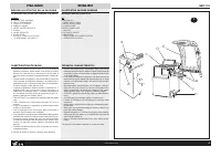
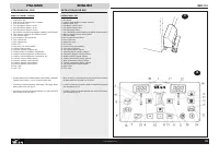
ITALIANO ENGLISH SBM 155 4 COD. 655632 Rev.0 1 DISEGNO ILLUSTRATIVO DELLA MACCHINA con indicazione delle principali parti componenti ai fini dell’uso LEGENDAA: INTERRUTTORE GENERALEB: CAVO DI ALIMENTAZIONEC: CRUSCOTTO PORTAPESID: PANNELLO COMANDIE: CARTER PROTEZIONE RUOTAF : FLANGIAG. CALIBRI AUTOMA...
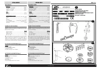
ITALIANO ENGLISH SBM 155 6 COD. 655632 Rev.0 DATI TECNICI DIMENSIONIAltezza Max (con carter aperto) ............................................... 1800mmProfondità (con carter aperto) ................................................ 1260mmLarghezza (senza flangia) .....................................
ITALIANO ENGLISH SBM 155 8 COD. 655632 Rev.0 1800 900 500 1260 500 5 DISIMBALLO » Dopo avere tolto l’imballaggio (ved. fig.5) assicurarsi del’integrità della macchina controllando che non vi siano parti visibilmente danneggiate.In caso di dubbio non utilizzare la macchina e rivolgersi a personalepro...