ASSEMBLAGGIO; ASSEMBLY; Fit the blade guard to the shaft arm with screws in a position - Oleo-Mac TR95E 6004-9032T - Manuale d'uso - Pagina 10


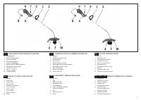


Indice:
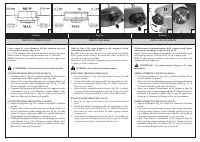
- Pagina 2 – TEHNIČKI PODACI; INTRODUZIONE; DATI TECNICI; Lpa; TECHNICAL DATA; ВВЕДЕНИЕ; GİRİŞ; RUS; UVODNE NAPOMENE
- Pagina 4 – Italiano; NORME DI SICUREZZA; English; SAFETY PRECAUTIONS
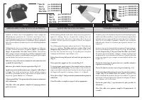
- Pagina 8 – ABBIGLIAMENTO PROTETTIVO DI SICUREZZA; Franćais; SAFETY PROTECTIVE CLOTHING
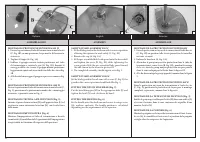
- Pagina 10 – ASSEMBLAGGIO; ASSEMBLY; Fit the blade guard to the shaft arm with screws in a position
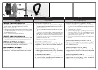
- Pagina 14 – Correct adjustment of the harness permits the brush; OPERAZIONI PRELIMINARI
- Pagina 18 – MANUTENZIONE
- Pagina 20 – CERTIFICATO DI GARANZIA; Français; CERTIFICAT DE GARANTIE; SERIAL No
10
Italiano
ASSEMBLAGGIO
English
ASSEMBLY
1A
1B
2
3
4
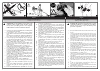
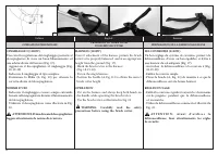
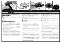
MONTAGGIO PROTEZIONE SICUREZZA 900 W
1. Fissare la protezione al tubo di trasmissione tramite le viti
(C, Fig. 1B), in una posizione che permetta di lavorare in
sicurezza.
2. Togliere il tappo (A, Fig. 1A).
3. Infilare il gruppo mozzo-testina-protezione nel tubo
di trasmissione e serrare la vite (B, Fig. 1B); durante il
serraggio della vite, tenere il gruppo mozzo-protezione
leggermente spinto nel senso indicato dalla freccia in Fig.
1B.
4. Alla fine del montaggio il gruppo si presenta come in Fig.
2.
MONTAGGIO PROTEZIONE SICUREZZA 1100 W
Fissare la protezione al tubo di trasmissione tramite le viti (C,
Fig. 3); posizionare la protezione in modo che, a montaggio
avvenuto, si presenti come in Fig. 4.
MONTAGGIO TESTINA A FILI DI NYLON (Fig. 5)
Inserire il perno fermo testina (H) nell'apposito foro (L) ed
avvitare in senso antiorario la testina (N) con la sola forza
delle mani.
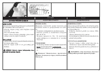
MONTAGGIO IMPUGNATURA (Fig. 6)
Montare l'impugnatura sul tubo di trasmissione e fissarla
tramite viti (A), rondelle e dadi. La posizione dell'impugnatura
è registrabile in funzione all'esigenza dell'operatore.
ASSEMBLAGE
SAFETY GUARD ASSEMBLY 900 W
1. Fit the blade guard to the shaft arm with screws in a position
allowing the operator to work safely (C, Fig. 1B).
2. Remove the cap (A, Fig. 1A).
3. Fit the pre-assembled hub-head-guard onto the drive shaft
and tighten the screw (B, Fig. 1B); while tightening the
screw, push a little the pre-assembled hub-guard toward
the side shown by the arrow in picture 1B.
4. The completed assembly should appear as in Fig. 2.
SAFETY GUARD ASSEMBLY 1100 W
Fit the blade guard to the saft arm with screws (C, Fig. 3); the
guard in the correct position should look like Fig. 4.
FITTING THE NYLON LINE HEAD (Fig. 5)
Put the head fixing pin (H) in the appropriate hole (L) and
tighten the head (N) anti-clockwise by hand.
FITTING THE HANDLE (Fig. 6)
Fit the handle onto the shaft arm and secure it using screws
(A), washers, and nuts. The handle position is calculated
depending on the requirements of the operator.
MONTAGE DE LA PROTECTION SECURITÉ 900W
1. Fixer la protection au tuyau de transmission à l'aide des vis
(C, Fig. 1B) en position telle à vous permettre de travailler
en toute sécurité.
2. Enlever le bouchon (A, Fig. 1A).
3. Aboucher le group moyen-tête-protection dans le tube de
transmission et serrer la vis (B, Fig. 1B); pendant le serrage
de la vis, tenir le group moyen-protection un peu poussé
dans le sens indiqué par la flèche dans la figure 1B.
4. À la fin du montage le group apparâit comme dans la figure
2.
MONTAGE DE LA PROTECTION SECURITÉ 1100 W
Fixer la protection au tuyau de transmission à l’aide des vis
(C, Fig. 3); positioner la protection de façon pue, à montage
completé, se presente comme dans la figure 4.
MONTAGE DE LA TETE AUX FILS DE NYLON (Fig. 5)
Enfilez le goujon qui va bloquer la tête (H) dans son orifice (L)
et vissez à la main, dans le sens contraire des aiguilles d'une
montre, la tête (N).
MONTAGE DE LA POIGNEE (Fig. 6)
Montez la poignée sur le tuyau de transmission et fixez-la avec
les vis (A), les rondelles et les écrous. La position de la poignée
se règle selon les exigences de l'opérateur.
Franćais
"Caricamento dell'istruzione" significa che è necessario attendere finché il file non è caricato e pronto per la lettura online. Alcune istruzioni sono molto grandi e il tempo di caricamento dipende dalla velocità della tua connessione a Internet.
Sommario
TEHNIČKI PODACI I BIH SRB HR INTRODUZIONE Per un corretto impiego del decespugliatore e per evitare incidenti, non iniziate il lavoro senza aver letto questo manuale con la massima attenzione. Troverete su questo manuale le spiegazioni di funzionamento dei vari componenti e le istruzioni per i neces...
WARNING: The brush cutter, if properly used, is a quick, confortable and efficient tool. So that your work is always pleasant and safe, please respect the following safety precautions scrupulously. 1 - Keep this manual on hand and consult it before each use of the tool. 2 - The brush-cutter must o...
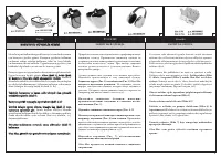
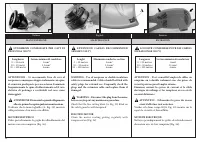
8 Italiano ABBIGLIAMENTO PROTETTIVO DI SICUREZZA Franćais 1 2 3 English SAFETY PROTECTIVE CLOTHING Quando si lavora con il decespugliatore usare sempre un abbigliamento protettivo di sicurezza omologato. L’uso dell’abbigliamento protettivo non elimina i rischi di lesione, ma riduce gli effetti del d...
Altri modelli di tagliaerba Oleo-Mac
-
 Oleo-Mac BC 22 T
-
Oleo-Mac BC 24 T
-
 Oleo-Mac TR 111E
-
 Oleo-Mac TR111E 6005-9003T
-
 Oleo-Mac TR92E 6004-9004AT