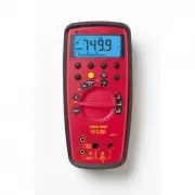
Amprobe 37XR-A - Manuale d'uso - Pagina 3

6
Measuring Inductance
See Figure
-10-
1.
Set the Function Switch to
mH
or
H
.
2.
If
RANGE
is displayed, press the
RANGE
button to enable autoranging.
3.
Connect the Test Leads: Red to
H mA
, Black to
COM
4.
Turn off power to the circuit being measured.
5.
Free at least one end of the inductor from the circuit.
6.
Connect the Test Probes across the inductor.
7.
Read the display.
Measuring Frequency
See Figure
-11-
1.
Set the Function Switch to
Hz
.
2.
If
%
is displayed, press the yellow button to display
Hz
.
3.
If
RANGE
is displayed, press the
RANGE
button to enable autoranging.
4.
Connect the Test Leads: Red to
Hz
, Black to
COM
5.
Connect the Test Probes to the signal source.
6.
Read the display.
Measuring Dutycycle
See Figure
-12-
1.
Set the Function Switch to
%
.
2.
If
Hz
is displayed, press the yellow button to display
%
.
3.
Connect the Test Leads: Red to
%
, Black to
COM
4.
Connect the Test Probes to the signal source.
5.
Read the display.
Measuring dBm
See Figure
-13-
The 37XR-A measures dBm relative to 1 mW referenced to 50
:
. That is,
10 dBm = 10 mW, 0 dBm = 1 mW, -10 dBm = 0.1 mW, etc.
1.
Set the Function Switch to
dBm
.
2.
Press the yellow button. The display shows
dBm
to verify the selection.
3.
Connect the Test Leads: Red to
, Black to
COM
4.
Connect the Test Probes to the signal source.
5.
Read the display.
Testing Logic Levels
See Figure
-14-
The 37XR-A tests logic levels for both TTL and CMOS logic. The meter displays
9
plus a
for a high-level (true) condition. The meter beeps and displays an
9
and
a
for a low-level (false) condition. See
Specifications
for the logic 1 and logic 0
voltage limits. Out-of-limits indications are dispalyed as
9
only, no
or beep
occur
.
1.
Set the Function Switch to
LOGIC
2.
Press the
TTL CMOS
button to display the selected type.
3.
Connect the Test Leads: Red to
, Black to
COM
4.
Connect the black lead to logic common.
5.
Connect the red lead to the logic test point.
6.
Read the display.
"Caricamento dell'istruzione" significa che è necessario attendere finché il file non è caricato e pronto per la lettura online. Alcune istruzioni sono molto grandi e il tempo di caricamento dipende dalla velocità della tua connessione a Internet.
Altri modelli di multimetri Amprobe
-
 Amprobe 34XR-A
-
 Amprobe HD110C


